Miscellaneous Failures In Robotics
Miscellaneous Failures In Robotics
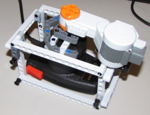
Unfortunately, no explosions. However, parts do fly. If you pay close attention, you’ll see a gear get thrown during the first attempt, just before everything goes wrong.
Looks like I need to be able to lock the arm in place, or it’ll keep popping up.
September 6, 2009 No Comments
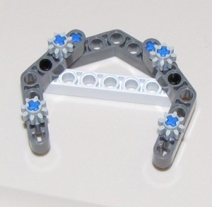
Stylish and Functional
Well, okay, it’s only stylish if you close your eyes.
And as far as functional, I don’t know. I haven’t hooked it up yet.
But it looks like it fits the paddle! Which, of course, means that it’ll break into pieces as soon as I try to make it go…
September 5, 2009 No Comments
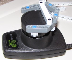
Now the gears are turning…
Gears! That’s the key!
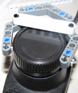
The Atari 2600 Paddle has a series of ridges and grooves around the spinner knob. I was trying to get things to grab onto those grooves, but for some reason, I didn’t try the gears in the kit.
Until now.
Groovy.
September 5, 2009 No Comments
Atari 2600 Pong Paddle Zones
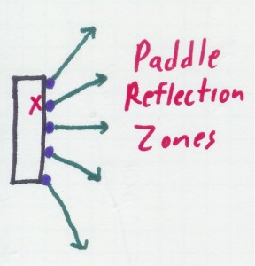
One thing that I haven’t mentioned regarding the “physics” of Pong is that the paddle causes a total change in the motion of the ball. The walls reflect the ball like a real-world wall would, giving the ball a negative slope of the same value. The paddles, however, assign a new slope, based on where the ball hits.
If the ball hits high on the paddle, the ball gets a steep upward slope. If the ball hits toward the middle of the bottom half, the ball takes a 45 degree downward trajectory, and when it hits the middle, it will go straight across.
The diagram above is for illustrative purposes only, as I’m pretty sure there are 7 possible angles, not the five shown: Three up, three down, and straight. Seven makes the most sense when considering the game programming, as well. There are seven possible angles for each side, which makes 14 possible angles in normal play. Add in straight up and straight down, which are possible on some of the other variations of Pong on the cartridge, and you get 16 total angles, which can be stored neatly in a four-bit nibble.
Another point to note is the X on the upper half of the paddle. That represents the location of the follow point on the CPU paddle. The Atari will try to always seek that point to the ball, which means that most of the time, when the CPU paddle hits the ball, it’ll bounce it in an upper trajectory. However, in order to make it possible for the player to actually beat the computer, the CPU paddle can’t move fast enough to perfectly track the ball. The paddle is always too slow for the highest angles and will only be able to hit them if the ball reflects off a boundary wall close enough to the CPU side so it doesn’t have to chase it that far. At higher speeds, it can be too slow for any angle, potentially even straight across.
Anyway, the relevance of this to my project is that I’m not going to attempt to calculate the trajectory after hitting the paddle. It would be too much work to determine the location of the different reflection zones, and wouldn’t be of any real benefit.
September 4, 2009 No Comments
And another reason…
Another good reason to build this robot:
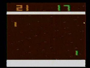
I suck at Pong.
And that’s with a non-jittery paddle.
September 4, 2009 No Comments
Break It Down
Let’s break down that spec and take a closer look at the components.
Visual Data Collector
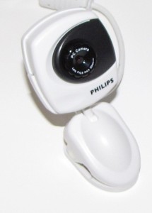
The Visual Data Collector is a standard PC USB Webcam. Hopefully it will meet my requirements. If not, I have a backup plan.
Computer Vision Textbook
I plan to use OpenCV to process the input from the Visual Data Collector. It seems fairly straightforward to use, even when the task is complex. Of course, I haven’t actually programmed anything using it yet, so we’ll see. I’ve skimmed the book and have some idea of where to start.
Communications Interface
The Newtonian Motion Decoder and Processor will talk to the Real Time Autonomous Interaction Device over Bluetooth. I’ve never programmed anything using Bluetooth. I pretty much stick to TCP/IP. This will be an interesting change.
Real Time Autonomous Interaction Device
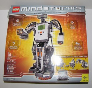
The Realtime Autonomous Interaction Device will be constructed using a Lego Mindstorms robotics kit. I bought this about a year ago and only built the sample car thing that everyone builds first. I’ve never tried anything on my own. Until now.
Simulator Control Interface
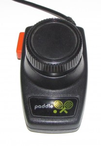
This device houses an analog potentiometer, which will function as the interface to the Newtonian Motion Simulation.
Low-Resolution Newtonian Motion Simulator
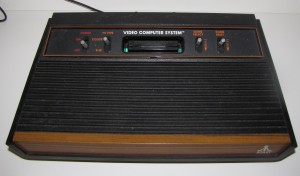
This Video Computer System excels at running simulations of Newtonian motion, so I have chosen it as the primary Newtonian Motion Simulator for this project.
Newtonian Motion Software
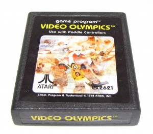
The read-only memory chip on this circuit board contains fifty different kinds of Newtonian motion simulations, however, for the purposes of this project, I will only be focusing on one of them.
Hardware
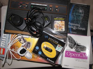
Here’s a jumble of most of the equipment I’ll be using during this project. Not pictured are the display screens for the Low-Resolution Newtonian Motion Simulator and the primary and secondary Decoder and Processor devices, as they are not very portable.
So, there you have it!
September 3, 2009 No Comments

